Part Design Best Practices: Optimizing For Plastic Injection Molding
High quality, efficient tooling relies heavily on good part design, advanced skills in mold design, and the manufacturing of the tool. An injection mold is a high-precision tool that must be rugged enough to withstand hundreds of thousands of high-pressure molding cycles.
By optimizing your part design and focusing on consolidating many key features, you can reduce your overall investment costs significantly. Adhere to the most common best practices in designing your part for the plastic injection molding process and your product or part quality, consistency and reliability will meet your expectations.
Wall Thickness
Next to resin selection, maintaining uniform wall thickness throughout your design is critical. This will help you develop stronger, better looking parts while also aiding in the overall look and feel by reducing blemishes that may occur from stresses during the injection molding process.
Wall thickness will often determine the mechanical performance, cosmetic appearance, moldability and cost-effectiveness of your plastic injection molded custom parts. Achieving optimal wall thickness is a balance between strength and weight which represents both durability and overall cost. During your design phase, give careful consideration to wall thickness in order to minimize expensive tooling changes down the road. Utilizing ribs, curves and corrugations can help you to reduce material costs and still provide rigid strength and durability in you plastic molded parts.
• A 10% increase in wall thickness provides approximately a 33% increase in stiffness with most materials
• Core out unneeded thickness and wall stock
• Use ribs, stiffening features and supports to provide equivalent stiffness with less wall thickness
Draft
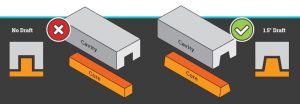
Draft is an angle incorporated into your part design to aid in the ejection process from the mold machine. Plastic parts should be designed with draft to prevent sticking and ejector pin push marks on the show surface during the molding process.
Angles or tapers that you incorporate to key features of your parts such as ribs, walls, posts and bosses that lie perpendicular to the parting line of your part will help to ease the ejection process and eliminate problems when running your injection molded plastic parts.
Less draft will sometimes lead to damaging of your parts during ejection. Also, with plastic molded parts with little or no draft, a mold release agent may have to be used which can cause unwanted reactions and blemishes and may produce additional costs to your finished plastic parts. A draft angle of 0.5° is the minimum draft needed for most applications. Draft angles of 1.5° to 2° per side are standard for plastic injection molding. For surfaces that will be textured, a 3° – 5° draft angle is required.
Runners and Gates
Runners and Gates must be designed and incorporated into a mold to ensure that a consistent flow of material fills the mold at the right pressure. A Gate is the connection between the runner and the molded part. The location and size of the gate is integral to the molding process. Runners and gates control the flow of the molten material through the mold and into the cavity to create your final plastic part.
Sprue – the main channel in which molten resin enters the mold. This channel is typically larger ensuring that enough material is able to enter the cavity to fill the cavity completely.
Runner System – the runner system connects the sprue to the gate.
Gates – at the opposite end of the sprue, the gates are applied to the runner controlling pressure and flow of molten material. We utilize several gate options to ensure that your part can be filled as completely and consistently as possible.
Gate Location – the location of your gate has a direct impact on moldability. The best positioning is often a balance between ease of molding and part performance.
Gate Scar – gates can leave minor blemishes so it is important to gate into a non-cosmetic area or where it will not affect part function.
Tight Tolerances
With every injection molder you will hear the term “Tight Tolerance”. Unfortunately, that term is thrown about loosely. If not performed correctly, a tight tolerance part can lead to loss in performance or even part failure.
Knowing how to safely and effectively reach exact specifications takes a skilled team and advanced manufacturing technologies. Generally speaking tight tolerance parts for injection molding is + /- 0.002 inches. Many factors are put into play such as materials, part complexity, tooling and of course the injection process.
Starting with a good part design will ensure tight tolerance repeatability, improved manufacturability and reduced costs of your plastic injection molded parts. Size, Geometry and Wall thickness requirements have an impact on tolerance. Thicker walls produce different shrink rates depending on the material, making repeatability difficult.
Before manufacturing, address and analyze your parts making sure to receive both a mold flow analysis and Design for Manufacturability review will help ensure a successful injection molding process and reduce costly delays.
• Utilize low-shrinkage materials for parts with tight tolerances.
• Avoiding tight tolerance areas around the alignment of the mold halves (parting line) or moving mold components such as sliders.
• Design your parts to avoid tight tolerance in areas prone to warpage or distortion.
Ribs
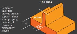
Often used for structure reinforcement, ribs allow greater strength and stiffness in molded plastic parts without the need to increase the wall thickness. Thicker ribs will often cause sink and other cosmetic problems on the opposite side surface to which they are attached.
As a general rule, design ribs that are approximately 60% of the joining wall thickness for minimum risk for sink marks. Glossy materials, however, require a thinner rib (40% of wall thickness). Keep in mind thin ribs may be more difficult
to fill.
Proper rib design involves five parameters:
• Thickness – Affects cooling rate and degree of shrinkage which may cause warp.
• Height – Should not exceed 3x the rib-base thickness.
• Location – Ribs added to uncritical areas can actually reduce impact resistance.
• Quantity – It’s easier to add ribs than remove them so they should be used sparingly and added as needed.
• Moldability – Thin ribs can be difficult to fill so to be sure, obtain a manufacturability analysis.
Bosses
Bosses are used for locating, mounting and assembly. Following the guidelines for boss design will have an impact on your final part. Wall thickness and Height are the biggest factors.
Wall Thickness – the wall thickness around a boss design feature should be 60% of the nominal part thickness, if that thickness is less than 1/8”. If the nominal part thickness is greater than 1/8” the boss wall thickness should be 40% of the nominal wall.
Height – the height of the boss will also have a role. As a general rule, the height of the boss should be no more than 2-1/2 times the diameter of the hole in the boss.
Undercuts
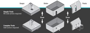
An undercut is any indentation or protrusion that prohibits an ejection of a part from a one-piece mold. Most commonly categorized by either an internal undercut or external undercut and requires an extra part to capture the detail as part of the mold.
Undercuts typically lead to increased mold complexity and can lead to higher mold construction costs. Usually, a simple re-design of your parts to eliminate or minimize undercuts can lead to lower cost tooling and a more efficient molding process.
When an undercut feature cannot be removed from the part design, it will most likely require internal mold mechanisms to help facilitate the ejection. Typically, the mechanisms consist of side-action slides, jiggler pins, lifter rails, collapsible cores and unscrewing mechanisms. When possible, design your part to eliminate undercuts as they will add cost to the mold. Mold makers may not be advanced enough and will put limits on undercuts.
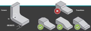
Corners and Transitions
Corners – sharp corners can cause molded-in stress from resin flow. It is important to minimize this stress by using rounded corners which also helps to maintain consistent wall thickness. Make the outside radius one wall thickness larger than the inside radius to maintain constant wall thickness through corners.
Transitions – sometimes it’s necessary to transition from thicker walls to thinner ones. Again, sharp corners cause molded-in stress from resin flow. Round or taper the thickness of your transitions to minimize molded in stresses and stress concentration associated with abrupt changes in thickness.
Conclusion
Adhere to best practices in designing your part for the plastic injection molding process. Consider the following “checklist” as a baseline to meeting your part expectations.
Wall Thickness
• Maintain uniform Wall Thickness throughout
• Utilize Ribs to reinforce walls without adding to thickness
• A 10% increase in thickness = 33% increase in stiffness
• Core out unneeded thickness and wall stock
Draft
• Maintain a minimum of 0.5° draft angle on all features perpendicular to the parting line. 1° – 2° is ideal.
Tight Tolerances
• Utilize low-shrinkage materials for parts with tight tolerances
Ribs & Bosses
• Design ribs and bosses to approximately 60% of the joining wall thickness for minimum risk for sink marks.
Undercuts
• Undercuts will add cost to the mold. Minimize them when you can. Otherwise, there are no limits.
Corners and Transitions
• Use gradual transitions if wall thickness must change.
• Corners: R1 + T = R2
DOWNLOAD: Designing for Manufacturability Guide
Interested in obtaining more advice? Reach a Technical Engineer at sales@xcentricmold.com, or call (586) 589-4636

