Hand Pull
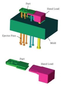
Portion of the custom injection mold that is used for creating undercuts in plastic parts. See Fig.1
Slide

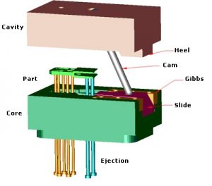
Portion of custom plastic injection molds that is used for creating undercuts. Required for automatic injection molds. See Fig.2
Gibbs
Portion of the custom injection mold that holds the slide down so the cam can actuate it. See Fig.2
CAM/HORN PIN
The cam, commonly referred to as Horn pin, is used to actuate the slide on an automatic injection mold. See Fig.2
Ejector Pins
Ejector Pins are used to push the part off the core half of the injection molds. See Fig.1 and Fig.2
Core
Refers to the side of the tool that the plastic part will stick to and is ejected from, also known as bottom half of the tool. See Fig.2
Cavity
Refers to the upper half of the injection mold, usually the show surface of the finished product. It is mainly concave. There is not as much standing core outs on this side of the tool. Therefore, the part will generally not stick to it when the injection molding machine opens the mold. See Fig.2
Side Action

Is the term used for slides and/or hand pulls used in the injection mold build process where undercuts in the part are present See Fig.1 and Fig.2
Heel Block
Heel blocks are used to keep the slide in the forward position when the molding machine is closed on the mold. See Fig.2 for Visual.
Part
Refers to customer’s custom plastic part to be made.
Tooling
Refers to the injection mold that is created to make plastic parts in the molding process
Shrink Rate
Refers to how much the plastic material will shrink after cooled. The shrink rate of the plastic is added to the part before the mold is designed. Every plastic material has its own shrink rate ranging from .001 per inch to as much as .060 per inch. Most shrink rates fall in between .004 and .021.
Gate
This is the location where the plastic enters into the cavity of the mold. Types of gates include: sub, edge, fan, cashew and XME exclusive vestige free edge for perfect shear
Vestige
Material or witness of material protruding from gate area after gate runner has been removed from the injection molded part.
Shear
Friction produced by speed and pressure. Too much shear during injection molding can cause the plastic material to burn while too little can cause the material to freeze off, causing a short shot.
Runner
A channel cut into custom injection molds in which plastic travels from the injection molding machine, through the sprue, through the runner and then through the gate, ultimately filling the part.
Short Shot
Is the result of a plastic part not filling completely during the injection molding process, including some or all of the details.
Sprue
The Sprue is perpendicular to the runner and is the channel that links the injection molding machine nozzle to the runner.
Undercuts
Referring to the portion of the designed component where a slide or hand pull is required to create holes, windows or clips that are not in the line of draw.
Core Outs
Refers to the portion of a part that is gutted out in order to achieve uniform wall thickness. Core outs have no end use or function other than lightening the part and thus reducing warp.
Line of draw
Line of draw is the direction in which the two custom injection mold halves will separate from the plastic part, allowing it to be ejected without any obstructions from metal creating the undercuts.
Piece Price
Refers to the cost of each plastic part as produced in the injection molding process.
SLA
Stereo Lithography Apparatus uses 3D printing technologies such as laser sintering and electron beam melting.
FDM
Fused Deposition Modeling uses three dimensional printing technology. The prototype parts are made by fusing layers of ABS plastic together, much like an inkjet printer functions, but laying plastic instead of ink.
Operator
A person used to run a plastic injection molding machine.
Thin Wall Molding
Thin wall molding is the molding of plastic parts with wall thicknesses .005 to .060.
Draft
Refers to portion of injection molded part that has a taper or angle on the side wall. Designers should incorporate draft to all plastic parts. See here for tips.
Stock Safe
Refers to the amount of metal left on the mold in order to tweak in a dimension. An example of stock safe is leaving material on a diameter of boss that requires a tight tolerance. As a rule of thumb, it is cheaper to remove metal than it is to add it.
Bulk Pack
Refers to shipping plastic parts in a box without any form of stacking.
Reverse Engineering
Refers to the process of taking an existing plastic part and creating a 3D solid model for duplicating in the injection molding process. Sometimes the design may include custom changes from the OEM
Sink Marks

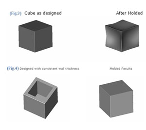
Refers to areas of the molded part where the plastic sinks below the surface due to un-uniform wall sections, thick wall sections and rib/boss to thickness ratios being off. See Fig.3
Warp
Refers to area of a injection molded part that distorts during cooling or molding, causing undesired results in the finished product. Usually caused by un-uniform wall sections. SeeFig.5 for prevention.
Ribs
Refers to thin bladed features on a part that are used for strengthening wall sections and bosses. Also, used to minimize warp. See Fig.6
Boss
Refers to round protrusions on plastic parts and molds. See Fig.7
Wall Thickness
Refers to the thickness of the cross section of the plastic part. See (Fig.9)
Additional Resources
Use the icons below to easily navigate to additional resources

