Gating System For Plastic Injection Molding: Sprue, Gates and Runners
Sprue
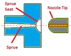
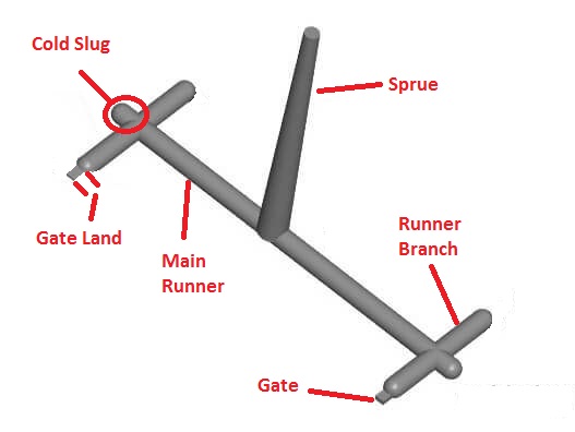
First, every mold has a sprue. This is the contact point between the machine and the mold. The sprue has a concave spherical seat where the molding machine nozzle tips seats off. It is important that the nozzle tip and the sprue seat have the same radius. If they do not seat off properly then material will leak at this point and parts will be inconsistent. From here, the molten plastic travels through the sprue where it enters the runner system. There are exceptions, on large parts the sprue can also act as gates and runners. This is called direct sprue gating.
Runner
Next, the plastic flows from the sprue into the runner system. The runner is the channel that feeds directly into the gate of each part. If the Injection Mold only has one cavity then there will only be one branch to the runner. If there are multiple cavities, then multiple branches will have to be engineered to ensure proper balance of flow. This way each cavity gets the proper amount of material. When designing a runner it is important to include a cold slug at every point there is a hard transition between branches. The reason for this because as the molten plastic flows through the runner system, it begins to cool. The cold slug is considered an area where this cold plastic is dumped in order to prevent it from entering the gate.

Gate
Last, the plastic enters into the gate. This is where a lot of problems occur in the injection molding process. Gates can be tricky, but understanding their purpose can help in designing a proper gate for a plastic injection molded part. First, many think the larger the gate the better. Although this may assist in getting the material in the cavity, it often leads to undesirable vestige that has to be hand worked as a secondary operation. This is called gate trimming.
Gate Sizing for Plastic Injection Molding
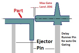
The illustration above shows a gate land that is way too long. In this scenario the process Tech will have to increase the molding pressure to overcome the frozen (plastic) gate at point of entry. This will in turn cause the material to degrade due to too much shear heating (friction). In addition, this gate will wear out over time. To avoid this, it is best to use as small a gate as possible. The trick to smaller gates is reducing the “Gate Land”. This is the area where most toolmakers and injection molding companies make a mistake. The reason for this is because the plastic virtually freezes off at the gate when the land is too large. Typically the land should be no more than .006″ wide. This is not a typo, the runner should come all the way up to the part.
By following the guideline above, there will be virtually no shear as the plastic enters in through the gate and into the cavity.

Gate Location
The best gate location on any part is usually where the thickest wall section is. However, it is important visually the plastic flowing into the cavity from the gate. Best practice is to place a gate in front of a standing core on the tool. This will cause the plastic to disburse evenly, preventing gate blemishes and jetting. Jetting is when the plastic shoots through the gate and creates a snake like tail as it races to the far side of the cavity. This material will freeze before the rest of the cavity is full, causing a snake like vestige in the part. To over come this, a Fan Gate is used. A Fan Gate will disperse the plastic material outward, thus preventing jetting. Other gates include Sub gates, Cashew gates and Hot Runner Systems.
Plastic Injection Molding Gate Types
Edge Gates
Edge gates are the preferred gate for injection molding companies, as they offer a wide range of flexibility for filling a part. Not only are edge gates affordable to manufacture, but they are easy to modify or change on the fly. Following the guidelines above, will ensure success every time. For high volume injection molders, a simple delayed ejection can be added to either the part or the runner to cause the gate to automatically detach. This is a better replacement to the traditional Sub or tunnel Gate because it will never wear out and offers perfect shear conditions.
Sub or Tunnel Gate
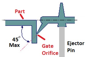
Sub Gates or tunnel are used in high volume automation where automatic de-gating is preferred. These gates tunnel under the tool steel into a wall section. As the part ejects the tunnel gate is sheared off as the ejector pin pushes up on the runner causing the gate to rip at the opening of the gate orifice. These gates do exactly what they are intended to however, that does not come without a price. Sub gates are expensive to manufacture and even more expensive to repair. Furthermore, they often add challenges to the molder as it takes more pressure to overcome Bernoulli’s theorem. “Pressures are least where velocities are greatest; likewise, pressures are greatest where velocities are least”. As the plastic travels down the funnel velocity is decreased. This in turn causes the plastic to freeze and pressure needs to be increased to over come. Eventually leading to excessive wear.

Cashew Gate
Cashew gate is another style of tunnel gate, where its shape resembles a cashew. This allows for tunneling into a part where the surface is parallel to the runner.
Hot Tip
Hot tip gating is where a hot manifold keeps the material hot and molten ready for every shot. They have a very tiny orifice and freeze off just enough to close the gate during cooling. The gate land is usually a maximum of .006″ depending on the grade of material. The benefit of this type of gate is that it reduces scrap produced by a runner and sprue and leave a very small gate vestige.

Other Gates and Runners
Over the years many have come up with some fancy names for gates and runners. They claim better fill conditions. However, the rule is simple. Keep it simple and follow the max gate land guideline above.
